|
BACK
OF THE METER
Figure
2-2 shows the connectors
on the back of the
meter. Table 2-2
gives a brief description
of each connector
at the back of the
meter. Refer to Figure
2-3 for dc-power
connection information.
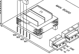 Figure
3.1
Connectors
(AC-powered)
|
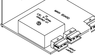 Figure
3.2
Connectors
(DC-powered)
|
|
Connector
|
Description
|
|
J1-1
J1-2
J1-3
|
AC
high connection
(NC on DC-powered
units)
AC low connection
(+ input on DC-powered
units)
AC ground (DC-power
return on DC-powered
units).
|
|
J2-1
J2-2
J2-3
|
Display hold
input (active
low) --connect
to J2-2 to hold
meter reading.
Peak and valley
readings are
continuously
updated during
display hold
even though display
is on hold.
Ground.
Display blank
input (active
low) -- connect
to J2-2 to blank
meter display. |
|
J4-1
J4-2
|
+ TC input.
- TC input (red
wire) |
Main
Board AC Power Jumpers
To check voltage jumpers,
or to change from 115
V to 230 Vac:
Disconnect
the AC power from
the meter.
Remove
the front lens, if
present.
Pull
the meter forward,
out of its case.
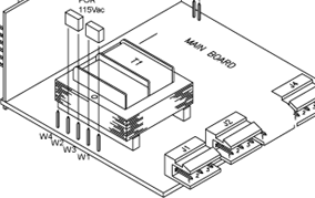 Figure
3.3 115Vac
Jumpers (Default)
|
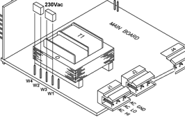 Figure
3.4 230Vac
Jumpers
|
S51,
-S4 Jumpers
The
S51 Jumpers is at the
front of the meter
near the digital isplay.
The S4 Jumpers is on
the side of the main
board (see igure 3.5).
(Defaults are in bold
and italic.)
Disconnect the
main power from the
meter.
Remove the front
lens, if present.
Pull the meter
forward, out of its
case.
S51-S4
Jumpers Table
3.2
|
Jumper
|
Description
|
|
S51
|
installed:
removed:
|
front
panel buttons
locked out
all buttons
operable. Jumper
placed in storage
position on one
PIN only. |
|
S4
|
installed:
removed:
|
calibration enabled
calibration
disabled. Jumper
placed in storage
position on one
PIN only. |
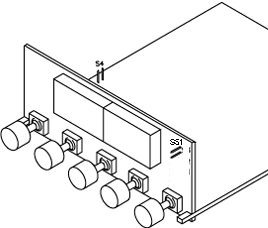
Figure
3.5
S51, -S4 Jumpers
General
Specifications
Microprocessor
based
Input
type:
Type
J, DINJ, K, T, E,
N, R, S
Max
Error:
▒ 1 deg C (▒ 1.8
ºF)
Accuracy at 25
ºC: ▒ .5
deg C (▒ .8 ºC
for DINJ)
Cold-junction
compensation tempco:
0.07ºC/ºC
|
Thermocouple
Types Range
|
|
|
Range
|
|
Type
|
Deg
C
|
DegF
|
|
J
|
-210
-346
|
760
1400
|
|
DIN
J
|
-200
-328
|
900
1652
|
|
K
|
-270
-454
|
1372
2500
|
|
T
|
-270
-454
|
400
752
|
|
E
|
-270
-454
|
1000
1832
|
|
R/S
|
-50
-58
|
1768
3214
|
|
N
|
-270
-454
|
1300
2372
|
Display
Type:
7 segments red or green
4 digit
Height:
0.56in
(14.2mm)
Resolution:
0.1º or 1º
resolution
Power
115 or 230 Vac
▒15% (2 Watt max.)
Frequency
50 or 60Hz
Isolation
354V peak per IEC
spacing
NMR 60dB
CMR 120 dB
DC voltage
10-32Vdc isolated to
300Vp
Environmental
Operating temp:
0╨60ºC
Storage temp:
-40 to +85ºC
Relative humidity:
95% at 40ºC (non
condensing)
Case
Newport
DIN 4896-100
Panel
cutout
1.77
X 3.62 in (45 X 92mm)
Depth behind bezel:
3.94
in (100mm)
Material
94V-0
UL-rated polycarbonate
Meter
Dimensions Figure
3.6
|